Weldments
how to create custom weldment profiles in solidworks.
Overview
SolidWORKS weldment is a powerful tool for structural design. combined with other features, it provides flexibility and ease of use to the designer. Its simplicity makes it easy to customize and understand. The core idea is that cross sections will extrude along a wire frame to create a 3d model of the structure. Designers create multi-body parts by using library profiles. Solidworks has a set of libraries for standard structural sections. But designers can add their own sets to the library as well. In this SolidWORKS tutorial we will lean how to use SolidWORKS weldment profiles.
Benefits of Using Weldments Command
Weldment creates a multi-body part that is useful in drawing documents. But, the benefits don’t stop there.
- You can use pre-defined cross sections stored in a library for your organization.
- You can change the length, depth, or width of the structure without changing the profiles.
- You can use cut-list tables in drawings.
- And in simulation environment Solidworks uses correct mesh type out of the box.
Activate Weldment Tab
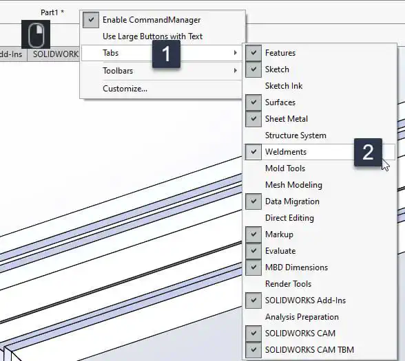
To add the weldment tab to your SolidWORKS graphics area follow these steps.
- Press
Ctrl + Nand in the window that appears selectPartand thenOk. - Then
Right-clickon the part name on top of the window and then pressTabsfollowed byWeldments(make sure weldments is checked)
Adding Weldment Cross Sections (Profiles) to SOLIDWORKS
In this section I will explain how to use solidworks standard libraries and how to introduce new profiles to the software.
What Are Cross Section Files?
Cross section profiles are sketches saved as .SLDLFP files. You can use them in the Weldment command.
They should have these properties:
- File extension should be
.SLDLFP - Should be closed sketches with at least one contour.
- Stored in weldment profile folder.
Where Is the Weldment Profile Folder?
To find the folder to save weldment profiles into follow these steps:
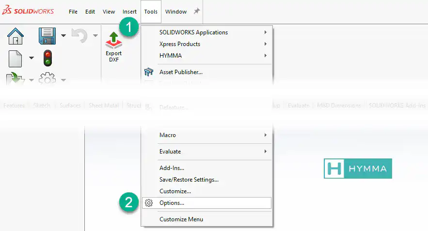
- Next to SolidWORKS logo select Tools.
- Select Options from drop down menu.
- In the window that appears select the System Options tab.
- From the list on the left select the File Locations.
- From the Show Folder For drop down on the top of the window select Weldment Profiles.
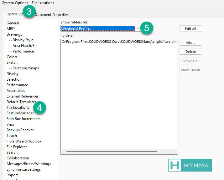
This is the folder you should copy the weldment profiles into. Folder structure is important.
Folder Structure of Weldment Profile Folder
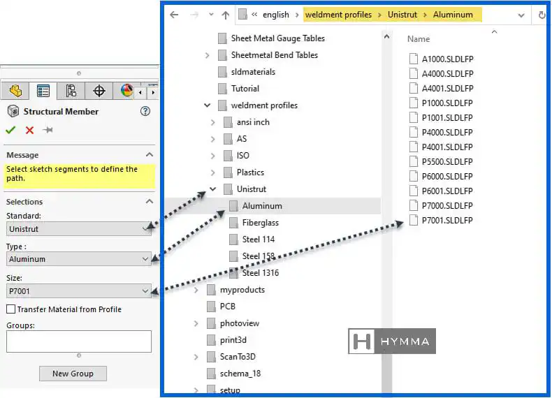
The Weldment command has three drop down menus.
- Standard
- Type
- Size
These are mapped to the content in the Weldment Profile Folder. As shown below.
How to Download a Standard Library of Weldments Profiles for SolidWORKS
Solidworks has a library of standard structural sections. But this library does not ship with the software itself. Users should download this library using the steps below.
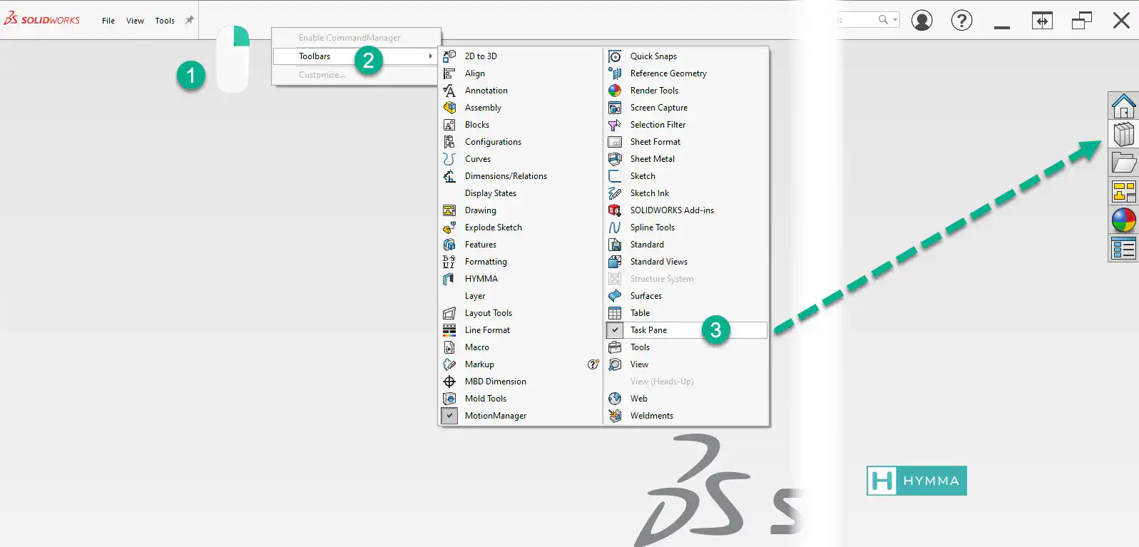
- Make sure Task Pane is accessible. From the top, right-click on a tab > Toolbars > Task pane.
- Click on Design library icon in task pane > expand Solidworks Content > weldments
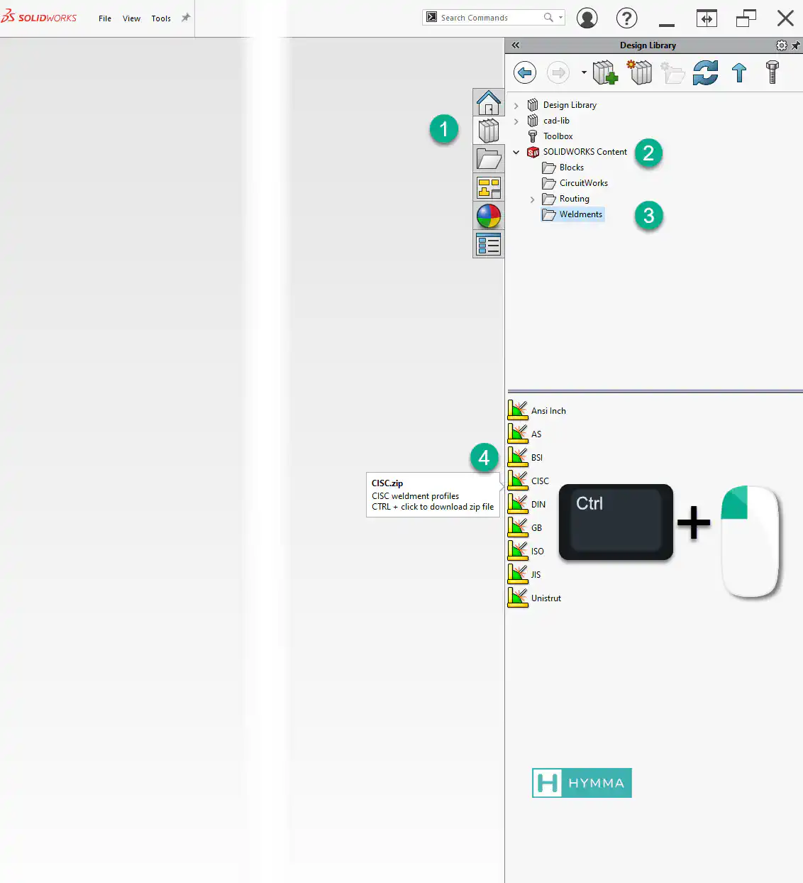
- To download a library, hold down Ctrl and click on the library you need.
- Save the zip files on your desktop.
Once downloaded, extract the content into the
Weldment Profile
. For example I have downloaded the Unistrut library and extracted the .rar file into the WELDMENT PROFILES and this is the folder structure:
📁WELDMENT PROFILES
|
|
📁---Unistrut                <-- Name of the (Standard)
    📁---Aluminum            <-- Member Family (Type)
    |       40x40.SLDLFP     <--Cross section files (Size)
    |       P7001.SLDLFP
    |
    📁---Fiberglass
    |       F1000.SLDLFP
    |       F1001.SLDLFP
    |
    📁---Steel 114
    |       A1000.SLDLFP
    |       A1001.SLDLFP
    |
    📁---Steel 1316
    |       P6000.SLDLFP
    |       P6001.SLDLFP
    |
    📁---Steel 158
            P1000.SLDLFP
            P1001 3.SLDLFP
How to Create a Custom Weldment Profile
Although SolidWORKS has a library of standard profiles you might need to create a separate library for your company
- Open SolidWORKS as administrator
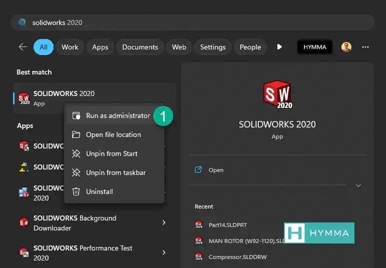 ImportantYou must open solidworks as admin to create a custom weldment.
 - Create a new Part Document.
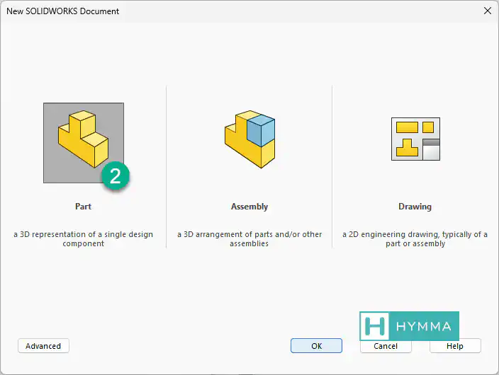
- Create a new 2d Sketch.
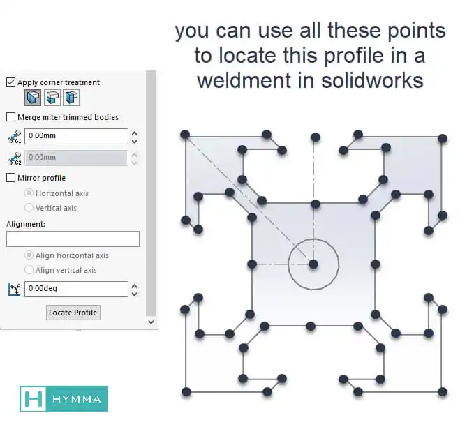
- Draw the cross section of the profile. Keep in mind that the origin of sketch is the default insertion point for the profile. You can use all the sketch points in the profile to locate the profile along the structure skeleton.
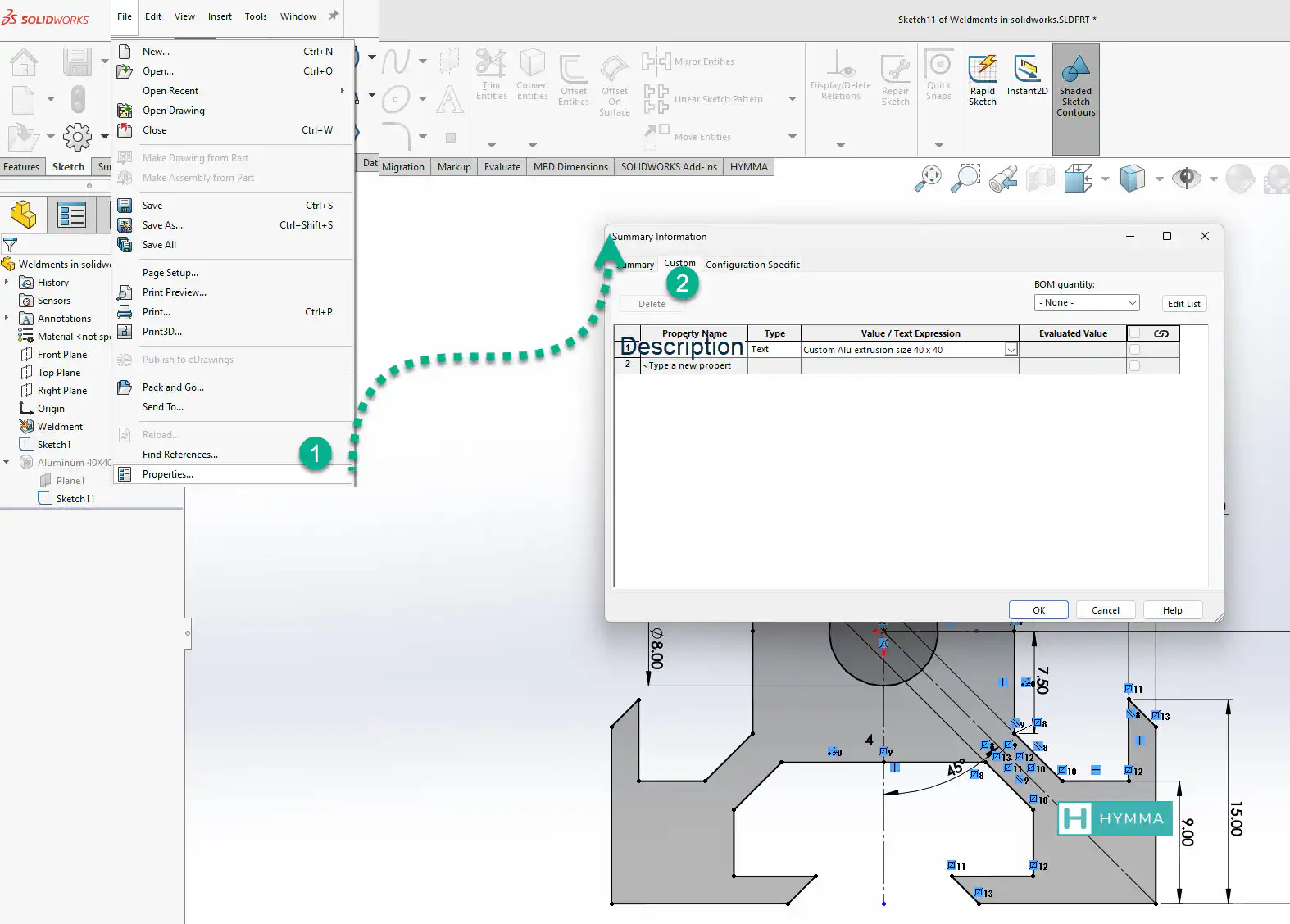
- add a custom property to the file titled Description.
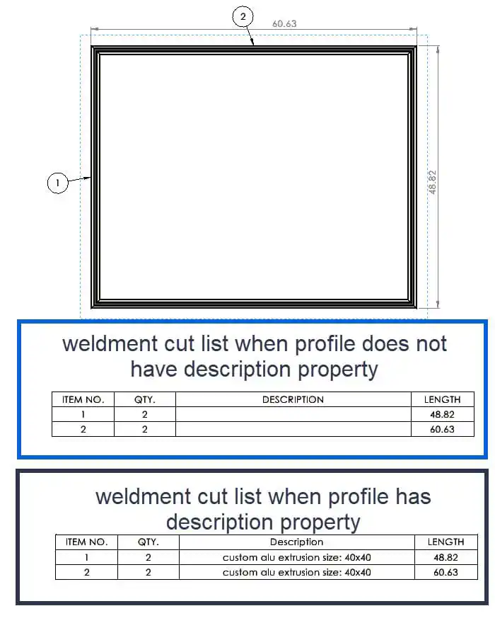
 ImportantSolidworks inserts the Description property value into the weldment cut lists.
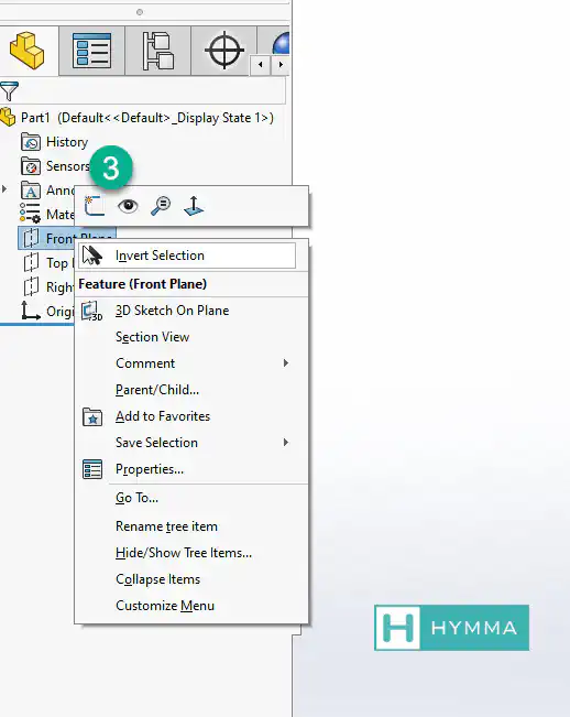
- Select and highlight the sketch in design tree.WarningYou must highlight the sketch in the design tree before saving the file with
.SLDLFPextension. Otherwise ,when inserting the profile, you will get an error that the library feature is empty. - Save the file as lib feat part
.SLDLFPin the weldment profile folder.
This youtube video explains the steps in this section. You might find it helpful.
Creating Wire-Frame as Skeletons
As discussed earlier, weldments profiles are closed sketches that get extruded along another sketch. The latter is a skeleton or wire frame. You need to create the skeleton using 2d or 3d sketches. In this tutorial we will use 3d sketch as it offers better control over the final design result.
- Press
Ctrl + Nand in the window that appears select a part document - Go to Sketch tab and expand sketch command and select 3D sketch

- Use hot-key L to draw a line.
- Pay attention to the plane of this sketch as it appears next to the pointer.

- To change the plane in 3D sketches rotate the model a bit and then use
Tabkey - Keep in mind that you can always use
Along x, y and zconstraint to further define your sketches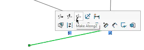
If you want to learn more about 3d sketches you can watch this video.
How to Use Weldment Command
make sure you have activated the weldment tab as discussed above
make sure you have a skeleton of your design following the steps mentioned above.
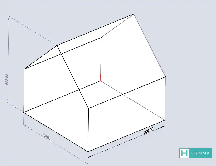
in the weldment tab click on the Structural Member command

in the property manager tab that appears on the left select the type of the profile you want. Keep in mind that you cannot choose more than one profile per “Structural Member” command. For example, if you need both I-beams and PFC in the same file then you should run this command once for each type.
Choose the standard, then the type of the profile (for example I-beam or pfc) and then the size of that profile.
Next you should define the groups. “Groups” in SolidWORKS weldment are lines that have at least one shared point. For example, a rectangle is a group of four segments. but parallel lines cannot be members of the same group. so, you need to create a new group for each line.
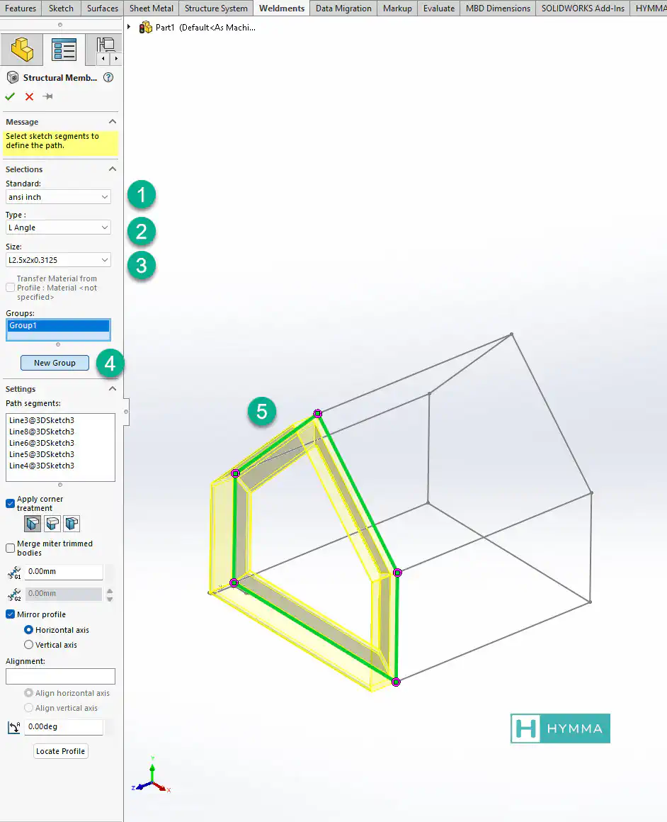
Each group has segments (members) that you select from the graphics area.
Once you define first group you will get access to more commands inside the property manager.
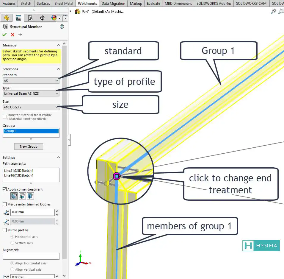
Apply Corner Treatment
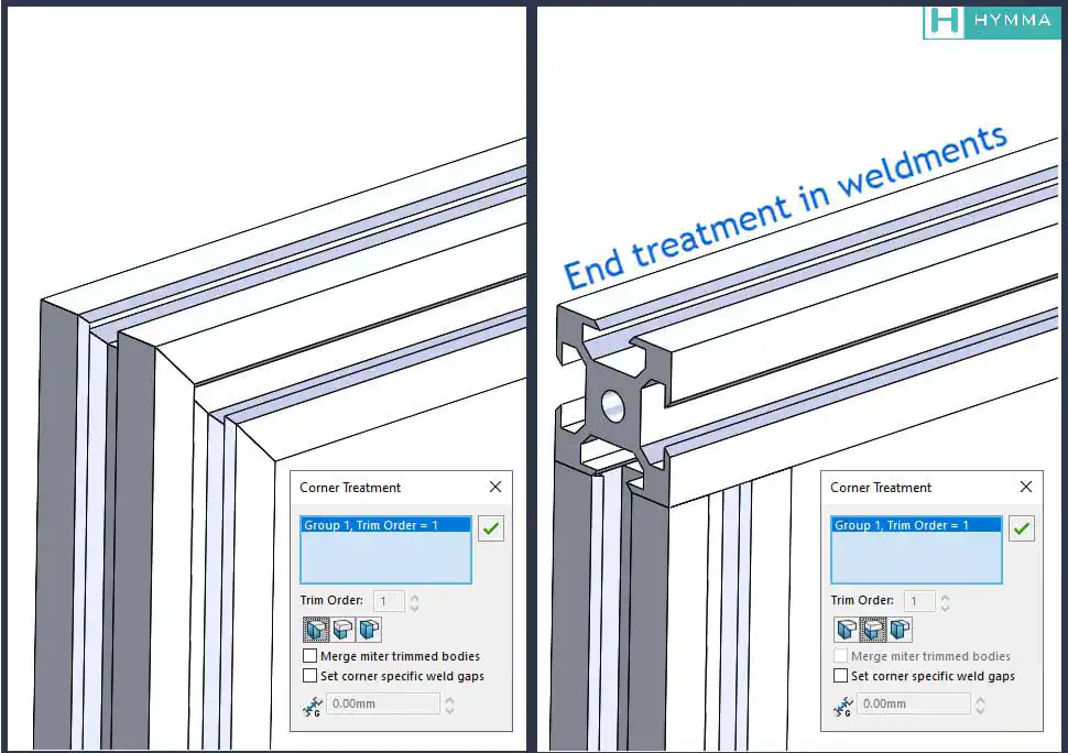
This checkbox allows you to cut the ends of each beam. You can define weldment gaps or Allow protrusion. The trim order defines which group of profiles are the dominant ones.
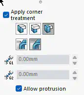
- The group with the higher order cuts through the ones with lesser orders.
- if two groups have the same order numbers they will be cut at 45 degrees each.
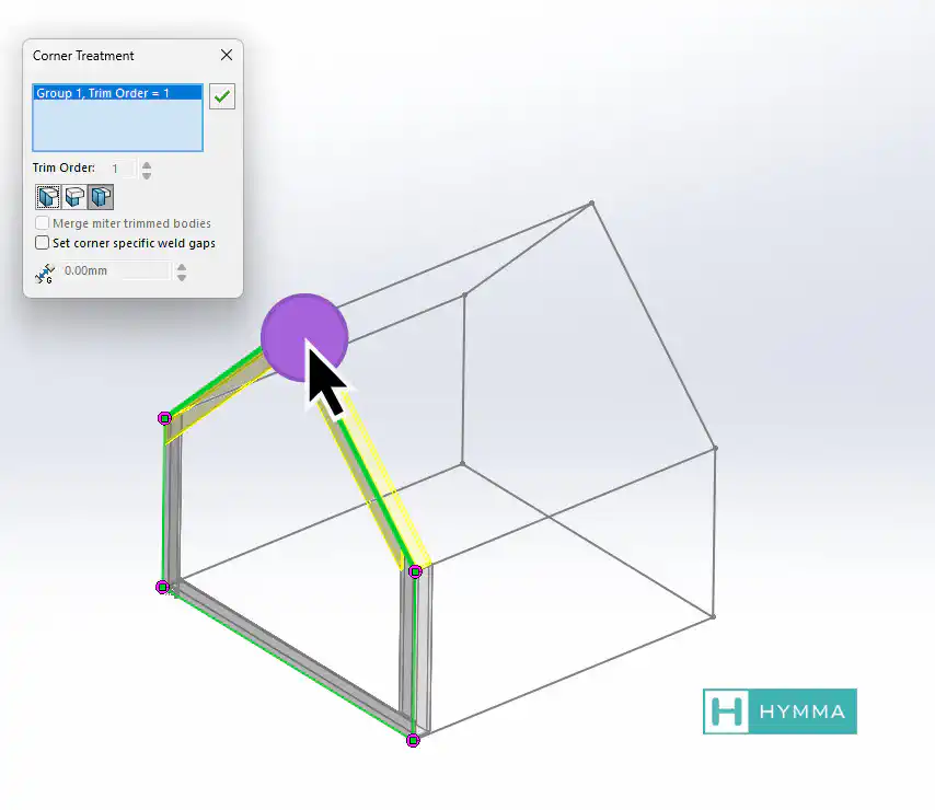
- You can always click on the shared point between two lines to control the cut orders. This point is highlighted magenta.
Mirror Profile
This command mirrors the profile either horizontally or vertically.
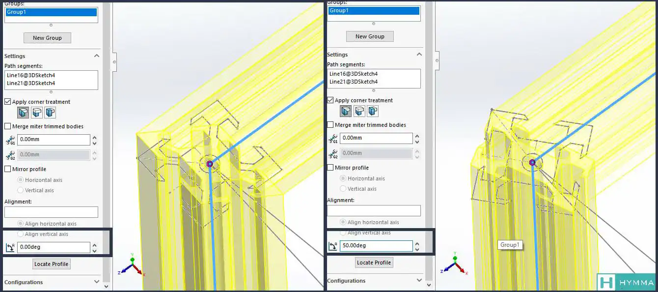
Rotation Angle
Allows you to rotate the profile along the line in that specific group.
Conclusion
We discussed how you can create a weldment profile and how you should use it in SolidWORKS. We cover all the important features and tips and tricks related to weldments in solidwroks. However, there is always more to learn. You can use links below to learn more about SolidWORKS weldment profiles and how to use them.
Frequently Asked Question
Also Read
Making a sheet for each body in a weldment drawing I