User Coordinate System
On creating coordinate systems in AutCAD. From annotations to dimensions to view-ports, coordinate systems affect many of the commands in AutoCAD. So creating a user coordinate system puts that control in my hands.
What Is the World Coordinate System
The default coordinate system in AutoCAD is called WCS (short for world coordinate system) and sets the point (0,0,0) in a drawing. The app reminds me of its importance by an icon in the left hand corner of the screen.
![]() .
To help with annotations and dimensioning I usually make custom coordinate systems too. These custom coordinate systems are called user coordinate systems or UCS for short.
.
To help with annotations and dimensioning I usually make custom coordinate systems too. These custom coordinate systems are called user coordinate systems or UCS for short.
How to Create a User Coordinate System
To make a coordinate system I should define its origin and two of its axis. For that I follow these steps:
- I turn Object Snap (OSnap) on using F3 to toggle the feature.
- Type
ucs - Pick a point on screen to define the origin of the coordinate system.
- I’d need two points to define the X axis. AutoCAD takes origin as the first point and I click a second time to create the axis.
- I repeat last step for the Y axis.
Then AutoCAD creates a new coordinate system at the origin and names it UnNamed. 😐
Assigning a Name to a Coordinate System
Assigning names to coordinate systems allows me to refer to them later. For example, I can make a view port that uses a specific UCS. To refer to that UCS I should use its name. This is how to name a UCS:
- I highlight the UCS icon
- type
ucs - type
NAfor Named - type
Sfor Save - I type in the name of the UCS
This will change the default name of the UCS to my specifications.
If you could not select the UCS icon. Follow these steps:
- Type
UCSICON - Type
Sfor Selectable - Type
Yfor Yes
What Are the Benefits of a UCS
Creating Running Dimensions
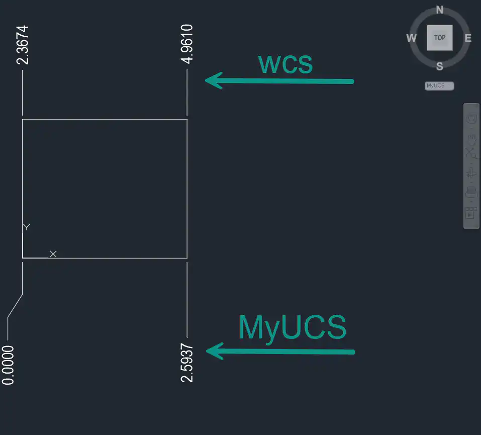
Also known as ordinate dimensions, running dimensions are common in mechanical drawings. In this command the zero is always the origin of the active coordinate system. So I create a UCS with the desired origin before running DIMORDINATE command.
In this image the upper row of dimensions are created when the WCS or World Coordinate System was active and the lower row were created when the UCS was active.

Control Annotation Angles
I have written about aligning text with view in the paper space in my other article Best way to create a view in a layout .